
RECURDYN MENU
RecurDyn/CoLink
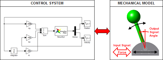
RecurDyn/CoLink enables you to model control systems which interact with your mechanical models. This plays an important role since design algorithms of a controller and the corresponding mechanical system (“plant”) should be evaluated simultaneously when simulating a computer-controlled system. The control system design environment is completely integrated within RecurDyn for easy operation.
Note: If you would like to instead use MATLAB/Simulink to create your control systems, you can use RecurDyn/Control to facilitate a co-simulation between RecurDyn and MATLAB/Simulink.
Benefits
- Controls engineers can efficiently test control algorithms early in the design process with highly nonlinear dynamic models.
- Mechanical systems may include control systems (whether electronic, hydraulic, etc.).
- The mechanical engineer and the controls engineer can join their independent design models.
- Controls engineers may struggle to develop robust controllers early in the design process because of the difficulty in constructing nonlinear dynamic models within controls software.
- These difficulties can be avoided by simultaneously developing the mechanical model in RecurDyn and the control system in RecurDyn/CoLink.
Process
- All mechanical components and constraints are modeled with RecurDyn.
- The control system can be modeled easily in CoLink.
- Plant outputs are passed from RecurDyn to CoLink at a constant sampling rate.
- Control outputs are passed from CoLink to RecurDyn at a constant sampling rate.
RecurDyn simulation of an inverted pendulum, controlled with proportional (P) control in upper window, and proportional integral derivative (PID) control in lower window. PID controller keeps pendulum upright with little oscillation.
Additional Example Application
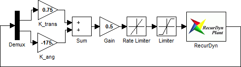
All-Terrain Vehicle Steering Control
RecurDyn/CoLink was used to model a driver’s steering input into the all-terrain vehicle shown above, allowing it to be simulated as it follows a predefined path over a rock-strewn course. The vehicle’s translational and angular deviation from the target path, plotted above, were used as inputs into the control system, shown below. Limiter blocks were added to model the actual limitations of both the driver and the vehicle.
More Information
- Request more information about this and other software modules.